

Top
Abstract
The Multi-Switch Interconnect Module (MSIM) for IBM BladeCenter is a switch module container that converts a stacked pair of high-speed I/O bays into two standard I/O bays. It is supported only in the BladeCenter H chassis. Two MSIMs can be installed in the BladeCenter H: one in the space of switch bays 7 and 8 and one in the space of switch bays 9 and 10. The MSIM accepts two supported standard switch modules and enables a blade server to have up to a total of eight network connections. To connect to the switch modules in the MSIM, a blade server must have a CFFh-type adapter installed.
Note: The MSIM is withdrawn from marketing.
Introduction
The Multi-Switch Interconnect Module (MSIM) for IBM BladeCenter is an innovative solution if you are looking to use additional standard form-factor switches in place of the high-speed switch bays in the BladeCenter H chassis. By using redundant MSIMs, you can deploy virtualization-ready solutions by providing up to eight Ethernet network interface cards (NICs) to each blade server in the chassis.
Figure 1 shows the MSIM.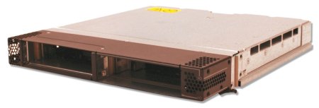
Figure 1. Multi-Switch Interconnect Module
Did you know?
Two MSIMs can be used in each BladeCenter H chassis, making it ideal for those who are looking for redundancy. The use of the MSIM to add four additional ports makes it ideal for application such as server consolidation and virtualization.
Up to two standard form-factor switches can be supported per MSIM, for a total of eight switches in the BladeCenter H chassis.
Part number information
Table 1 shows the part number to order this card.
Table 1. Part number and feature code for ordering
| Description | Part number | Feature code |
| Multi-Switch Interconnect Module for IBM BladeCenter | 39Y9314 | 1465 |
The part number includes the following items:
- One Multi-Switch Interconnect Module for IBM BladeCenter
- Multi-Switch Interconnect Module Installation and User's Guide
- The documentation CD
- Safety information
Features
The MSIM has the following features:
- Provides standard I/O module support in the high-speed switch bays of BladeCenter H
- Accommodates two standard I/O modules (Ethernet Switch Modules, Fibre Channel Switch Modules, or Pass-thru Modules), side by side
- Leverages the I/O design of BladeCenter H to provide increased connectivity to each blade
Operating environment
The expansion card is supported in this environment:
- Temperature: 10° to 35°C (50° to 95°F)
- Relative humidity: 8% to 80%, noncondensing
Supported BladeCenter chassis
Table 2 lists the IBM BladeCenter chassis that supports the Multi-Switch Interconnect Module.
Table 2. IBM BladeCenter chassis that supports the Multi-Switch Interconnect Module
Multi-Switch Interconnect Module for IBM BladeCenter |
39Y9314 |
N |
N |
Y |
N |
N |
The MSIM is a switch module container that converts a stacked pair of high-speed I/O bays into two standard I/O bays. Figure 2 shows the MSIM being installed into bays 7 and 8 of the BladeCenter H chassis.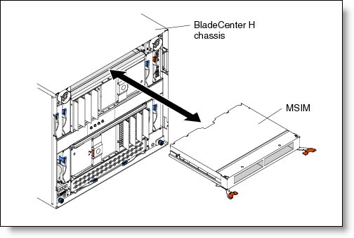
Figure 2. MSIM installed in bays 7 and 8 of the BladeCenter H chassis
Figure 3 shows how two MSIMs can be installed in the BladeCenter H: one in the space of switch bays 7 and 8, and one in the space of switch bays 9 and 10. The MSIM accepts two supported standard switch modules and enables a blade server to have up to a total of eight network connections. To connect to the switch modules in the MSIM, a blade server must have a CFFh-type adapter installed.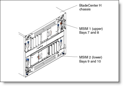
Figure 3. Two MSIMs installed in the BladeCenter H chassis
Supported expansion cards
To use the MSIM, each blade must have a supported CFFh expansion cards installed. Table 3 lists the supported CFFh cards.
Table 3. Expansion cards that can be used to connect to I/O modules in an MSIM
CFFh expansion card |
Part number |
Supported with MSIM |
2/4 Port Ethernet Expansion Card (CFFh) |
44W4479 |
Supported |
NetXen 10 Gb Ethernet Expansion Card (CFFh) |
39Y9271 |
No |
Broadcom 2-port 10 Gb Ethernet Expansion Card (CFFh) |
44W4466 |
No |
Broadcom 4-port 10 Gb Ethernet Expansion Card (CFFh) |
44W4465 |
No |
QLogic Ethernet and 4Gb Fibre Channel Expansion Card (CFFh) |
39Y9306 |
Supported |
QLogic Ethernet and 8Gb Fibre Channel Expansion Card (CFFh) |
44X1940 |
Supported |
4X InfiniBand DDR Expansion Card |
43W4423 |
No |
Voltaire 4X InfiniBand DDR Expansion Card |
43W4420 |
No |
QLogic 2-port 10Gb Converged Network Adapter (CFFh) |
42C1830 |
No |
Emulex Virtual Fabric Adapter (CFFh) |
49Y4235 |
No |
The ports on the CFFh expansion cards in each server are hard wired to specific bays in the switch modules in each MSIM. Table 4 lists the mapping of expansion card ports to the I/O bays of MSIMs.
Table 4. Mapping of expansion card ports to the I/O bays of MSIMs
| Port number of the CFFh expansion card | Corresponding switch module bay in the MSIM |
| 1 | 7 (upper left interconnect module bay) |
| 2 | 8 (upper right interconnect module bay) |
| 3 | 9 (lower left interconnect module bay) |
| 4 | 10 (lower right interconnect module bay) |
Supported I/O modules
Table 5 lists the supported standard form factor I/O modules and the MSIM bays in which they are supported.
For each of the expansion cards that support the MSIM (see Table 3), the MSIM supports I/O modules in the left bay, the right bay, or both bays of the MSIM. Table 5 summarizes this support. Because the supported expansion cards are Ethernet or Fibre Channel only, no SAS or InfiniBand switch modules are supported in the MSIM.
Note the following explanation when viewing the table:
- Right means that the module is only supported in the rightmost I/O slot of the MSIM.
- Left means that the module is only supported in the leftmost I/O slot of the MSIM.
- Both means that the module is supported in both the rightmost and leftmost I/O slots.
- No means that the module is either not supported or not recommended for performance reasons (for example, mixing a 4 Gb FC with an 8 Gb FC).
Table 5. Supported standard form factor I/O modules and the MSIM bays in which they are supported (left bay, right bay, both bays) for each expansion card
Ethernet switch modules |
||||
Cisco Intelligent Gb Ethernet Switch |
32R1892 |
Left |
Left |
Both |
Cisco Intelligent Gb Fiber Ethernet Switch |
32R1888 |
Left |
Left |
Both |
Cisco Catalyst Switch Module 3110G |
41Y8523 |
Left |
Left |
Both |
Cisco Catalyst Switch Module 3110X |
41Y8522 |
Left |
Left |
Both |
Cisco Catalyst Switch Module 3012 |
43W4395 |
Left |
Left |
Both |
Server Connectivity Module |
39Y9324 |
Left |
Left |
Both |
BNT Layer 2-7 Gb Ethernet Switch |
32R1859 |
No |
No |
No |
BNT Layer 2/3 Copper Gb Ethernet Switch |
32R1860 |
Left |
Left |
Both |
BNT Layer 2/3 Fiber Gb Ethernet Switch |
32R1861 |
Left |
Left |
Both |
BNT 10Gb Uplink Ethernet Switch |
32R1783 |
Left |
Left |
Both |
BNT 1/10 Gb Uplink ESM |
44W4404 |
Left |
Left |
Both |
Fibre Channel switch modules |
||||
Brocade 20-port 4Gb SAN Switch |
32R1812 |
Right |
Right¹ |
No |
Brocade 10-port 4Gb SAN Switch |
32R1813 |
Right |
Right¹ |
No |
Brocade Enterprise 20-port 8Gb SAN Switch Module |
42C1828 |
Right² |
Right |
No |
Brocade 20-port 8Gb SAN Switch Module |
44X1920 |
Right² |
Right |
No |
Brocade 10-port 8Gb SAN Switch Module |
44X1921 |
Right² |
Right |
No |
Cisco 4Gb 20-port Fibre Channel Switch |
39Y9280 |
Right |
Right¹ |
No |
Cisco 4Gb 10-port Fibre Channel Switch |
39Y9284 |
Right |
Right¹ |
No |
QLogic 20 port 4Gb Fibre Channel Switch |
26R0881 |
Right |
Right¹ |
No |
QLogic 20-port 4Gb SAN Switch Module |
43W6725 |
Right |
Right¹ |
No |
QLogic 10-port 4Gb SAN Switch Module |
43W6724 |
Right |
Right¹ |
No |
QLogic 4Gb Intelligent Pass-thru Module |
43W6723 |
Right |
Right¹ |
No |
QLogic 20-port 8Gb SAN Switch Module |
44X1905 |
Right² |
Right |
No |
QLogic 8Gb Intelligent Pass-thru Module |
44X1907 |
Right² |
Right |
No |
x
Table 5 (continued). Supported I/O modules and the MSIM bays they are supported in (left bay, right bay, both bays) for each expansion card
Pass-thru Modules |
||||
Optical Pass-thru Module |
39Y9316 |
Both³ |
Both³ |
Both |
Copper Pass-thru Module |
39Y9320 |
Left |
Left |
Both |
Intelligent Copper Pass-thru Module |
44W4483 |
Left |
Left |
Both |
QLogic 4Gb Intelligent Pass-thru Module |
43W6723 |
Right |
Right¹ |
No |
QLogic 8Gb Intelligent Pass-thru Module |
44X1907 |
Right² |
Right |
No |
Notes:
- When this 4Gb I/O module is used with the QLogic Ethernet and 8Gb Fibre Channel Expansion Card (CFFh), the card operates only at 4 Gbps.
- When this 8Gb I/O module is used with the QLogic Ethernet and 4Gb Fibre Channel Expansion Card (CFFh), the module operates only at 4 Gbps.
- When the Optical Pass-thru Module is installed in the right-hand MSIM bay (for use with a Fibre Channel expansion card), the Optical Pass-thru Module only operates at 2 Gbps. This is a limitation of the OPM.
Popular configurations
This section illustrates how the MSIM can be used in BladeCenter H configurations to add four extra ports to each server in the chassis.
Eight Ethernet ports per server
With the MSIM, it is possible to supply eight Ethernet ports to every BladeCenter server installed in the BladeCenter H chassis, as shown in Figure 4. In this configuration, each BladeCenter server has both a 2/4 Port Ethernet Expansion Card (CFFh) expansion card plus an Ethernet expansion card (CFFv or CIOv form factor, depending on the model of the server). Eight Ethernet switch modules are installed in the BladeCenter H chassis, four of them in MSIMs. All connections between the cards and the switch modules are internal to the chassis. No extra cabling is needed.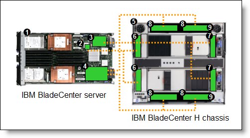
Figure 4. Using two MSIMs and eight Ethernet Switch Modules to route eight Ethernet ports per server
Table 6 lists the components that are used in the eight-Ethernet-ports-per-server configuration shown in Figure 4.
Table 6. Components used in the eight-ports-per-server configuration
Diagram reference |
Part number / machine type |
Description |
Quantity |
Varies |
IBM BladeCenter HS22 or other server that supports CFFh cards |
1 to 14 |
|
None |
Ethernet controller on the system board of the server |
1 per server |
|
Varies |
Ethernet CFFv or CIOv expansion card |
1 per server |
|
44W4479 |
2/4 Port Ethernet Expansion Card (CFFh) |
1 per server |
|
8852 |
BladeCenter H chassis |
1 |
|
Varies |
Support Ethernet Switch Modules routing signals from the integrated controller |
2 |
|
Varies |
Supported Ethernet Switch Modules routing signals from the CFFv or CIOv card |
2 |
|
Varies |
Supported Ethernet Switch Modules routing signals from the CFFh card |
4 |
|
39Y9314 |
Multi-Switch Interconnect Module |
2 |
Trademarks
Lenovo and the Lenovo logo are trademarks or registered trademarks of Lenovo in the United States, other countries, or both. A current list of Lenovo trademarks is available on the Web at https://www.lenovo.com/us/en/legal/copytrade/.
The following terms are trademarks of Lenovo in the United States, other countries, or both:
Lenovo®
BNT®
BladeCenter®
Other company, product, or service names may be trademarks or service marks of others.


